ERT (Electrical Resistivity Tomography) for Earthmat Design
Large capacity power plants are now being designed for meeting increasing energy demand and operational scale economy. These plants have large size grounding system and therefore optimization of safe earth mat is essential for economic design. Earth mat of a power plant has two objectives: to carry electric current into earth under normal and fault conditions without exceeding operating and equipment limits and to assure that a person in the vicinity of grounded facilities is not exposed to the danger of electric shock. The soil/rock resistivity is directly related to earth mat design parameters and has a critical role in economic design and in achieving the desired earth mat resistance with respect to ground. PSP/ Hydro power plants are in general located in rocky areas where higher resistivity values are encountered and denser grid is used for achieving desired earth mat resistance.
In general Wenner four electrode method is used for assessment of ground resistivity as per IS Code 3043- 1987 . This method gives apparent resistivity values and results are acceptable in soils where the ground is homogeneous. However in case of rocky area ground is not homogeneous and large resistivity changes are met in both horizontal and vertical direction. Simple geophysical resistivity measuring techniques can be utilized for resistivity measurements and details of true ground resistivity in vertical direction can be determined. However finer details cannot be measured.
ERT in comparison to conventional resistivity survey can provide finer details of ground resistivity to design a safe, economic and effective earth mat. This approach has been used at some Hydro Power and PSP projects.
Codes for Earth Mat Design and Resistivity Measurement
Following codes are under use for Earth mat design and for procedure of resistivity measurement at plant site.
Is code 3043-1987 (amendments issued in Jan 2010), code of practice for earthing: This code recommends detailed resistivity measurements in eight directions utilizing wenner electrode configuration.
IEEE Std. 80 2000 , IEEE Guide for Safety in AC Substation Grounding: This standard has detailed deliberations on resistivity measurement and recommends for adoption of highly refined techniques for assessment of finer details of resistivity for Earth mat design. Procedure for determining true resistivity using two-three layer earth model based on geophysical survey is suggested for a layered earth. Large numbers of available theoretical master curves with known parameters (resistivity and thickness) are compared with the measured apparent resistivity field data. After curve matching true resistivity and thickness of different layers can be determined.
IEEE Standard 81- 1983, IEEE guide for measuring earth resistivity, ground impedance and Earth surface potentials of grounding system: This standard recommends that detailed resistivity measurements are necessary if there are variations of resistivity with depth. The number of such readings should be greater where the variations are large, especially if some readings are so high as to suggest a possible safety problem.
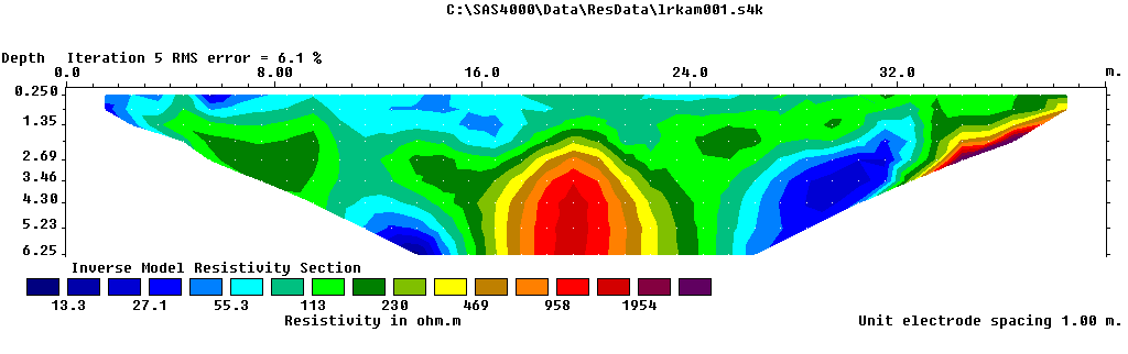
ERT at a Hydro Power Plant
High resistivity location not suitable for earthmat
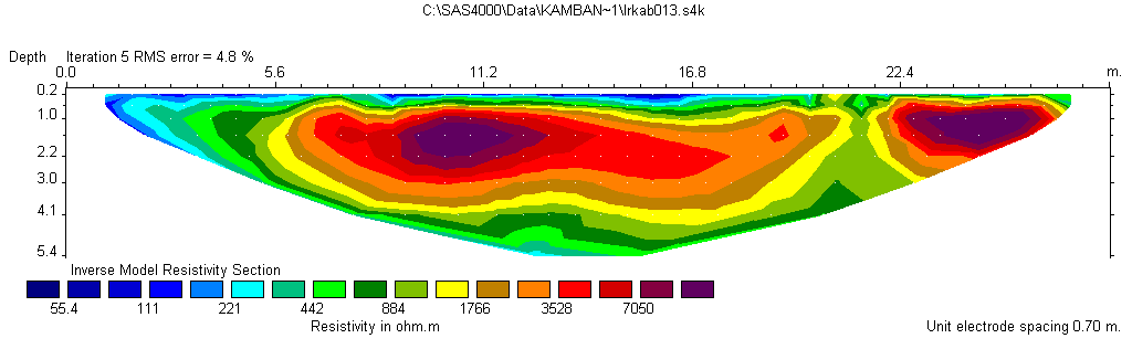
Low resistivity location suitable for earthmat
Applications
- Power plants
- Renewable energy farms
- Industrial plants
- Telecom towers
- Electrical distribution networks
- Data centers
- Lightning protection systems
- Railways and transportation infrastructure
Our Clients